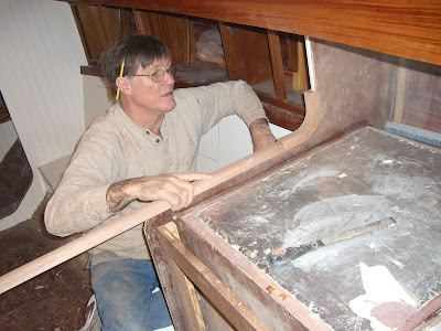
We have found that frequently in boat building there are certain aspects that seem daunting. Lots of head scratching and consulting with various wood worker and boat building friends, and then of course, trial and error (also known as the learning curve) always results in an answer.
Prior to applying the first layer of the cabin top, the outside of the cabin sides were veneered with the 3/16" solid mahogany. This will cover the plywood cabin sides that were previously layered and clamped to form the structural shape of the cabin.
The book matched piece was scribed to fit prior to being epoxied in place.
The cabin side and the piece were "wetted out" with epoxy, and clamped in the method described in the previous post.
Really cleans up the side....Richard will wait to apply varnish to the sides, since they will probably take a little abuse in the next phases.
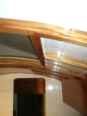
One design feature we really admire in classic boats is the cabin overhead being white painted v-groove to contrast with the bright beams. We ordered ship lap v-groove 5/16" meranti with about a 3" face (about 1/2" wider than vertical surfaces). Richard spent numerous hours prepping and pre-painting the face of the boards....this was to avoid masking to paint in place and not being able to get a nice clean line.
The frames were faired with the use of a batten to determine high spots. Starting in the center, the strips were butted tight. The location of the frames were marked, the painted scuffed up and 3M 5200 adhesive was applied to the boards. Plastic staples were used to secure the boards to the frames. Two layers of coldmolded 1/8" thick Western Red cedar will be applied over this base. This will made a very strong, rigid cabin roof.


The strips went on easily and smoothly.
The shape is very pleasing...the hatches are cut out cleanly.
So, one cool night we decided it was time to admire Richard's recent hard work.
We decided a nice bottle of wine was called for...it really highlights the nice lines, don't you think?
And it sets off the contrast of the beams and the v-groove....
Her first cocktail party....
Here you can see the slight difference in the size of v-groove faces.....
Loving the contrast.
Enjoying the view. If you use your imagination, you can be in a remote anchorage....
Loving the rounded top. Not disappointed at all in the changes we made to the cabin shape...
While waiting for lumber for the cold molding of the cabin roof, further trim jobs were completed inside. A small fiddled shelf was completed in the fore cabin.
Extra frames were shaped to the hull at equal spacing, between chain plate supports (dark) and cold mold frames (with deck supporting knees) as attachment sites for the sapele "ceiling" (the decorative side walls).
Slates of 5/16" sapele were milled and finished. They will be butted tight together, with a vent strip at the top and holes down into the storage under the settee. This creates a chimney type vent to help inhibit the growth of mold. Decorative brass screws will make the ceiling removable, if needed. We debated putting the ceiling in at all, but think the loss of about 1 1/2" of space on the pilot berth width will be worth the finished look.
Another seemingly major obstacle was how to tie the starboard settee front lip into the refrigerator trim.
All these pieces need to come together in an elegant way...
Many options were tried and tossed around......
Seemed to work....
Then discarded for some totally different idea.....
nothing seemed quite right for giving support at the front of the settee, and covering the raw edge of the v-groove board....luckily by the next day, a simple solution presented itself.....
The different trim moldings were milled from sapele. The U shaped pieces cover the edges of bulkheads (door trim and bulkhead at refrig).
The curved pieces were drawn onto solid wood, positioned so the grain follows the radius.
After being cut with a band saw, Richard devised a way to create the U shape on the outer aspect. The router bit is placed approx the right height above the router table.
He devised a fence and created it with the miter saw.
I'm not sure that this is an approved method of use for this tool.....
The fence will give support to the piece.
The blade is sticking out just enough.
Not to worry....the Kokanee beer in the background is not being consumed...just a box for scraps...
But the free hand nature of this part of the shaping doesn't thrill me....
Adult supervision is not over rated....Do not try this at home....
But it actually worked!
With a little tweaking it will fit perfectly, and match up with the straight pieces.
Once the groove matches up, the outside can be routed.
Not much to hold on to during routing...
The finished "outtie" angle.
"Innies" and "outties" both fit.....
Pretty sweet....
The pre-finished parts are applied to the frig box....
The frig box has had numerous coats of System 3 Linear Polyurethane applied to the inside. Lots of fairing and sanding between coats gives a very smooth, cleanable finish.
Simple is better, and classic looking. DOn't know how we got so side tracked with trying to find a way to make that joint look nice...note the sapele plugs still sticking out where the settee front trim is securely screwed to the settee. They will be cut and sanded and finished. And of course, the grain of the plug matches the trim...
Trim pieces are milled for the passage door, and finished prior to install.
Trim applied....
The next big hurdle was bulwarks.
These are the little side walls around the outside of the deck. They traditionally increase the freeboard, meaning a drier deck, and provide a rail for toes to wedge against in rough seas. They come in every shape and form imaginable...on many traditional wooden boats they are mounted to the structural frames that extend up above the deck level. Our frames stop at the deck level so this is not an option for us...also we felt that a contiguous deck would give a better seal at the hull. The deck/hull joint is a notorious leaky spot. Another option is to mount the bulwarks to brackets. Richard wanted the look of them mounted directly to the deck. The question was how to create them in the correct shape. They need to follow the sheer as well as the arc of the deck. We decided to do them painted, with an applied bright cap, and a bright rub rail at the deck bulwark joint.
The question is how to make all this happen...research in books and websites didn't seem to help. It was another case of "next build the bulwarks" ...
Richard came up with the idea of making blocks at each station on the deck edge. They were angled to accommodate the deck camber, and numbered to indicate their position. I came into the shop to help him use a batten at each station to continue the curve of the hull up onto the future bulwarks.
By wrapping the batten up the hull the shape of each block changed as it progressed around the hull. It seemed like a goofy way to come up with the angles but seemed to work well and created the correct tilt to the little wall.
Each block was hot glued to the previously fiber glassed deck. The blocks became a surprisingly strong base to clamp to across the long dimension, but would pop right off when hit from the side.....
Richard started by bending a 7/8 x 1 3/4 inch piece of VG fir around the blocks.....the first piece was do-able, but it quickly became apparent that there would be too much tension and spring back to stack the bent VG fir battens directly on top of each other, and not have them attempt to walk back into the woods..... it seemed the whole solid wall plan was at risk.....
Thanks to Jon Derry, a revised plan was developed. The VG fir would be placed in alternating layers with cut to shape 1/4" marine plywood. With the surfaces bonded together the plywood would stabilize the bent VG fir. Then a learning curve of the most effective way to scribe the plywood to shape ensued.
The edge of the ply was notched at each block so that it could be slid between the blocks.
It was then marked for placement and the shape of the hull side was marked.
This mark was cut on the band saw....
This gave the shape for the outside of the wall .
A 1 3/4" block run down the edge gave the mark for the inside curve, and the notches were cut off.
Each piece was taped into place and the next piece shaped. It started out taking about 20 min per 3-4 foot piece....he got quicker as he went.
The deck was taped to prevent the wall from sticking to the deck. He then used galvanized nails (in case one needed to cut off and left in place) to attach the first board in place. The ply was clamped in place to the first board. The next board was clamped to the previously epoxied layers. As use can imagine, this was a time consuming process, but effective. Occasionally the boards were reluctant to remain in place, and the spring back would slap Richard off the ladder, against the wall and to the ground. Thank goodness epoxy and clamps always win in the end.
The resulting wall is stripey, and will be removed from the protected deck by dislodging the nails.
The shape and tilt turned out awesome.....
The bulwark dies into the transom which will get cut down to size prior to capping.
The strips of hot glue peeled right up off the deck. That worked out very well, and the blocks were reused on the port side bulwarks.
As seen here, the deck protrudes about 1/2" out from the bulwarks. The scuppers (drain holes)were all marked for placement prior to removing the wall for cleaning up and shaping.
Richard has decided to make the bulwarks 1 3/4" at the bottom, and taper to 1" at top, under the 2" wide bright cap.
And here is a quick pic of the homemade clamps that were used to keep the boards under control while gluing. This style of clamp has proved highly effective for many parts of the project.The port bulwarks progressed in the same fashion, but much quicker.....the plywood pieces could be produced from the originals and just placed slightly further out with each layer. The shaping, cutting to length and height, and cleaning up of the walls is still to be done. We will save that for the next chapter.
Richard has put in 4600 hrs to date.


