Summer in the Flathead Valley is never the time to spend
pouring over my boat building blog....
pouring over my boat building blog....
now that fall/winter has arrived, I will proceed with the narrative for the pictures I hastily posted in September 1212, showing the progress up to the 5100 hr mark.
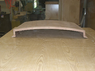
After the bulwarks were roughed in, Richard proceeded with the cabin top.
Since we had rounded the shape of the cabin to follow the deck,
we realized the top was now curved to the point where laminating up plywood was not an option anymore...
Back to the cold mold technique used on the hull....
The fore and aft strips seen above are the backs of meranti ship lap.
It was run to pattern (slightly wider than the other interior ship lap),
pre-painted to match the inside of the cabin, and laid over the varnish frames.
The junctions of the frames and ship lap were sanded to promote adhesion,
3M 5200 adhesive was used to bond (for strength and stretch),
and ring shank bronze nails used to attach the ship lap of the roof to the cabin frames.

Back to mixing epoxy...
The seams between the ship lap were sealed with very thickened epoxy
(the consistency of peanut butter) and sanded smooth prior to applying the cold molding epoxy.
Richard wanted to prevent oozing of this epoxy into the cabin and messing up the finished paint job.
Three layers of red cedar veneer diagonals
(5/16", 1/8", 1/8" thick)
were placed over the meranti to create a cabin top of 3/4" total thickness.
Of course, each layer was held flat and secure with about a million Raptor plastic staples...
After an initial sanding, the frames were marked off and ring shank bronze nails were used to do the final securing of the rigid top to the frames...
the top is very strong and rigid.
No worries about walking on this cabin top....
Fairing compound was used to cover the nail heads.
Thanks to all of my friends in the surgical department at KRMC,
for recycling the unused surgical basins.
Richard discovered that they make the best epoxy mixing bowls.
After the epoxy remnants dry, it just flakes right out, and the bowl can be reused numerous times.
You all have contributed a special part to our project...you must be motivated to assist me in "shoving off" as soon as possible...
thanks...
The sweetness of the fairing is always checked by feel.
View from the bow...
Richard decided to get a seamless fit of the ballast plug to the hull...
but the cross beam on the rack was in the way.
We started to look into having the ballast poured in lead,
and took a few pics to send to foundries for an estimate.
The fact that there is no flat surface on the keel, to pour to,
meant the estimates came back very steep.
May need to keep working on what our options might be...
In the meantime the whole family gets involved with the fitting...
I even managed a few knuckle busting bolts.
All the cross braces need to be removed....
Which makes her appear to be floating precariously in space...
The ballast plug was positioned....
And wedged up into place.
The slight uneven gap was remedied by adjusting the wedging...
and Richard assessed any need for scribing the final product.
A view from the front of the roughed in bulwarks.
Time to remove them and shape them.
Richard wanted the inside of the bulwarks to slightly angle out
and the outsides to follow the lines of the hull.
The finished bulwarks were to be 1" at top and 1 3/4" at the deck, with a bright cap on top.
Richard and buddie Randy pried the bulwarks off the masked deck,
and laid them out in the shop.
They were set up in the exact shape they took on the boat.
The layers of fir and 1/4"marine plywood, sawn to shape, once dry, really worked well
to keep the bent shape of the bulwarks.
The changing top and bottom dimensions of the bulwarks was marked at each station.
Then the electric plane was used to shape each piece.

The top of the cabin was sheathed with xynole and epoxy.
Our great friend Don came to assist with mixing and stretching on this two man job.
The extra set of hands means getting a beautiful seam...
And a smooth job....note the masked off cabin sides, companion way and deck.
The bulwark shaping is complete. Richard decided to use lag bolts and epoxy
to attach them to the deck.
Drilling holes and countersinking through the tall hardened wood/epoxy layers was a chore.
The bulwarks were positioned and bent into position by starting to clamp at the transom.
All available clamp points were utilized...
Even some created (across the cockpit)...
The front was pulled in across the bow,
while braces to the cabin sides were used to keep the curve true.
Then Richard did his handy-dandy trick of hot gluing blocks to the deck as
the final positioning clamping blocks.
The holes were extended into the deck at this point. Each hole in deck and bulwark was then filled with epoxy and re-drilled to prevent future water intrusion.
A frosting of micro-balloon thickened epoxy was used to fill any voids in prep for fairing.
All the bolt holes filled.
A custom long board, the perfect size for fairing bulwarks....
Just put a little sandpaper on back...
And start sanding,
and feeling.....and sanding....
It really does make a nice finished product.
During the beautiful summer months, she is pulled into the garage area.
We could check out her sheer line and decided to raise the back a slight bit to increase the curve of the sheer.
Gus even likes being closer to the action, and enjoys making paw prints from the epoxy dust.
Lots of custom work was needed for the hatch covers.
Each was laminated from ply to follow the camber of the deck.
Each hatch needed a self draining channel around it,
designed to keep water out of the lazarette.
The channel was glued and screwed in place.
A weep hole at the lowest point will drain into cockpit.
A lip was applied to the underside of the hatch, to fit into the track.
The stern lazarette has a track that drains side to side, and then to the front.
The hatch covers in place.
Templates for the settee cushions were made from newspaper rolls.
That helps with laying out exactly how much of the expensive foam will be needed.
The next step was trying to design and place the combings.
(the seat backs in the cockpit)
We decided to pretty much follow the shape of the bulwarks.
We needed to consider not making the seat portion too deep (for wedging feet across to the other side of the cockpit in rough seas), and getting the angle and height of the backrest correct for comfort.
I thought a hollow combing might provide a place to put cut outs for storage.
We played with many options, angles and ways to tie it into the cabin and the taffrail.
Nothing seemed to feel right.
Richard finally came up with a way to make them very solid
and create a sweeping comfortable curve by stacking and laminating 1" wide cedar into a small wall.
Note the angled blocks hot glued to deck as forms to create the desired shape.
The height is adjusted to allow for a nice sheer.
High enough in front to keep the cockpit drier, and still flow under the taffrail.

This shows the curve of the "backrest".
The deck was masked with tape prior to laminating the combing core,
so they could be popped off and worked on a bench.
Final shaping by hand and eye with a skill saw and sander.
Then after gluing up random width cedar to develop 1/4" thick panels,
he veneered 3 layers onto each side of the combings.
This gave super strength, rigidity, and shape retention to the walls.
The sides of the combings were ultimately veneered with 1/4" solid African mahogany.
And the caps were shaped from 1" solid stock sapele.
A solid block was shaped and angled to join the combing to the cabin.
The compound angle should help deflect water that is traveling down the deck in high seas.
The mahogany veneered combings and caps are nicely sanded prior to reinstall.
The finished product, varnished and set in place.
The cabin top and bulwarks were painted with System3 Water based linear polyurethane in Whitbey White. Rolled and Tipped, and sanded between coats.
Very happy with the contrast of the white and bright mahogany.
We decided to paint the transom under where the taffrail will go...
Not quite sure what design feature to do at the front of the bulwarks.
They are stopped short of the stem to accommodate the anchors.
The stem is where the bowsprit will sit.
Of course, we did some take some time during the beautiful Flathead summer to
treat the grandkids to a day of sailing with Don.
We enjoyed sharing our sailing with Jack and Olivia.
Back at the project, Richard trimmed the edge of the cabin with sapele.
And of course, Richard developed a wild looking clamp to hold it in place while gluing, screwing.
The pieces of trim were shaped into the crazy compound angles and sweeping curves.
Epoxy was applied to seal the underside of all pieces, to prevent water intrusion.
A person can at least be hopeful....
Richard finally rediscovered knee pads while working on the deck and trim work.
The need for a waterproof companion way cover made it
a design as the work was in progress type project.
A base for the turtle was designed.
It is the fixed cover at the forward edge of the opening.
The cover slides forward into the waterproof turtle.
Design, cut, design, cut.....
Richard decided to fancy up the turtle....
And fitted it to the cabin top.
Note that its asymmetrical on the bottom since it sits off center on the cabin top.
Of course, what cruiser would want anything but louvered doors for the ventilation of lockers?
Thank goodness for the CNC router, and
Mike doing a great job of designing the doors in CAD.
All doors have the same size stile and rail,
so the slat spacing needed to be adjusted to create different sized doors. Custom!
The slats were shaped.
All parts were varnished separately....
have you ever tried to varnished or paint an assembled louvered door?
Slats fit into prefinished stiles.
Checking the fit...
Another crazy jig....for rabbeting the stiles and rails.
The nicely varnished doors and turtle.
The caprail for the bulwarks was created by clamping a piece of sapele on each side of the bulwark top, then clamping and attaching a cap along the top.
The tops were sawn from 1" thick, long pieces, with scarf joints.
This gave a thick, shapeable cap in the precise shape needed.
A beautiful scarf joint....
A piece was clamped on each side of bulwark.
The top layer of the three part cap rail was clamped to the lower section.
And LOTS of clamps were used to get the bend.
That sweet scarf looks messy again.
A lot of curve to that rail....
Sweet lines...
Ready for the shaping of the top.
To create the sliding companionway hatch, Richard created a jig to cold mold over......
it was covered with wax paper to prevent the hatch from sticking to the mold.

The layers were then screwed to the over sized jig...
The edges with the holes would be cut off the sides.....
How to cold mold without a vacuum bag!
Marked with pencil to assist in fairing ....
Blocks screwed to the bench to hold the piece for long boarding.
A visit from Don and Will...and Will's wide angle camera.
Awe...the photo op...
Hatch and companionway assembled.
Wide angle of the interior....
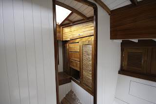
Some of the louvered doors installed.
Starboard saloon.
Looking toward companionway and "Don's berth".
From "Don's" quarter berth, across galley toward port side.
And of course, my beautiful refrigerator.


